You are not logged in.
- Topics: Active | Unanswered
#1 2017-03-17 01:47:52
- backXslash
- Member
- Registered: 2016-03-25
- Posts: 151
Rebuild Log: Or, What Tony Stark Did In A Cave With A Pile Of Scraps
I recently converted my top-down style printer (from my previous thread here) to a bottom up. What follows is a quick and dirty showcase of how I ended up, with some notes about design and execution choices thrown in for good measure. This rebuild resulted in the prints pictured in the "Successful Prints" thread here.
Here's the overall shot. The base is a nightstand I found at a local thrift store, it makes a pretty solid cabinet / base for just $11.

Here's a closer shot of the "business end". The 2x4 is bolted in with 6" long 1/4" diameter decking bolts with large washers on the inside to help distribute the clamping pressure. That provides a reasonably rigid spine for the Z axis to operate from. The build plate is suspended from hand-machined aluminum extrusion reused from my previous build. The aluminum along with the squishy bushings on the leveling screws allow a little extra flexibility at the build plate end and help to ensure a flush and even orientation of the plate relative to the vat. I actually have NanoDLP set up with the floor of the axis about 0.2mm lower than it actually is. I roughed up the build plate surface by lightly grazing it with the edge of a high speed cutting disk. Combined with the tension applied by the technically-too-low setpoint, the build plate is always ON the vat floor when I start a print, my prints STICK to the build plate, and I my failure rate is is almost non-existent. (I have had a few failed prints, but it was due to user error, not mechanical error).

Here's an even closer view of the business end. The coupler is (of course) spiral-cut aluminum for flexibility. You can see the anti-backlash setup on the ballscrew here as well as my top endstop. It's salvaged off a MakerBot Replicator 2, and it's hooked up so that the LED lights up when the axis hits it. I really just liked the fact that it lit up, let's be honest. You can also see the 0.9° stepper and stepper driver here.
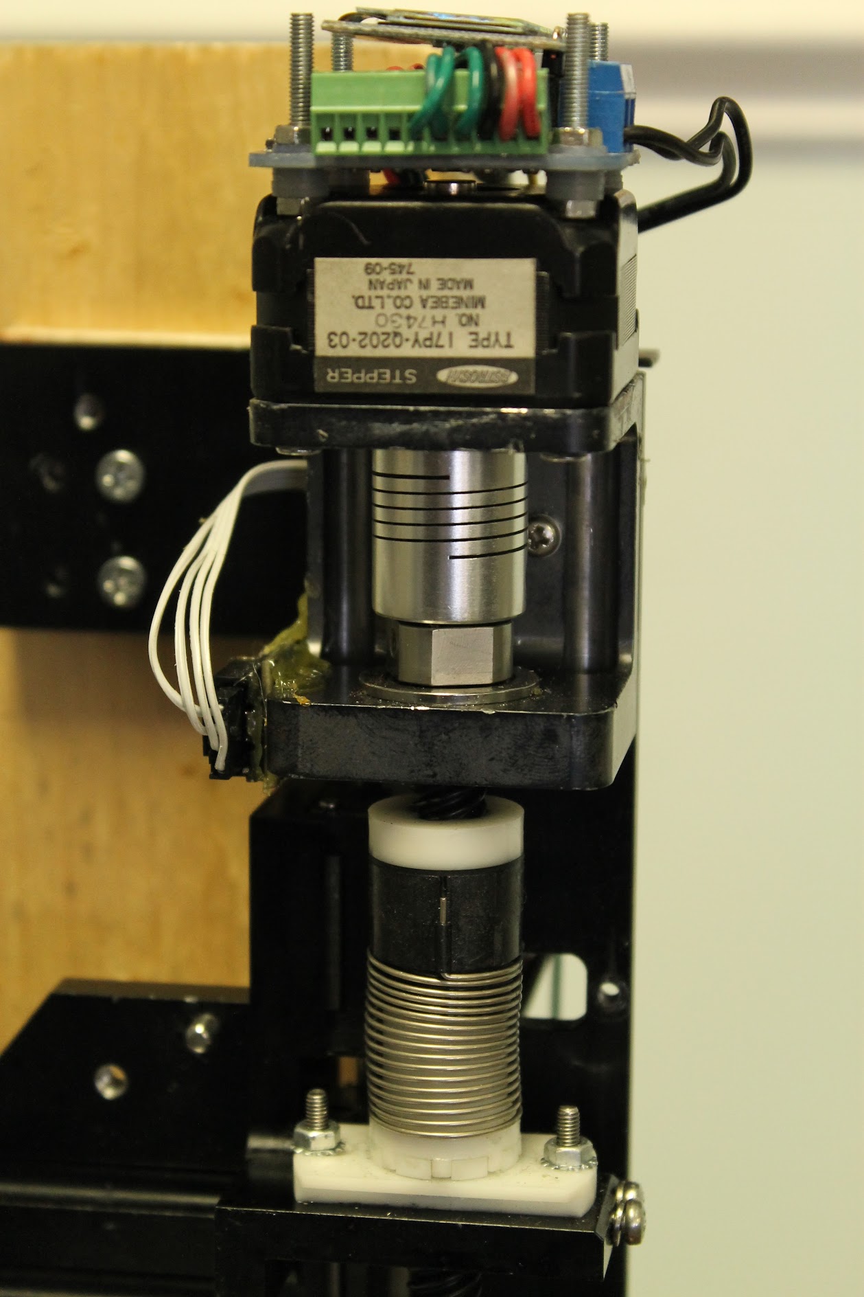
Here's an even closer shot of the "head" of the axis.

Here's a detail shot of the stepper driver. I attribute a good chunk of my print quality to this new driver set up. It's a Nano Zero Stepper by Misfit Tech. Specifically it's a closed loop stepper driver that allows the stepper to be treated more like an industrial servo, offering closed-loop control with up to 0.1 degrees of rotational accuracy. The LCD constantly displays the current axis position during a print (in relative rotational degrees from "0") as well as the current positioning "error". I print at 24 microns layer height, and hover at less than 1 degree of rotational error. On my axis one complete layer (24 microns) requires precisely 1.42 degrees of rotation. All of that adds up to mean that no matter what, my layers are never more than half a layer off. The driver is set up with an error pin as well which will trigger NanoDLP's hardware error pin if the axis binds or somehow becomes off position by more than 2.84 degrees (2 layers). This helps to add further security against failed prints.

Here's a detail shot of the gap under the driver and the diametric magnet attached the the motor shaft. The gap is there to properly align the encoder chip with the sensor magnet. You can also see the micro USB cable for the driver board. The driver has a DOS style command line interface accessible by SSH'ing into the RPi and invoking minicom. The command line interface allows one to change virtually any option on the driver, from microstepping to hold current to error threshold.
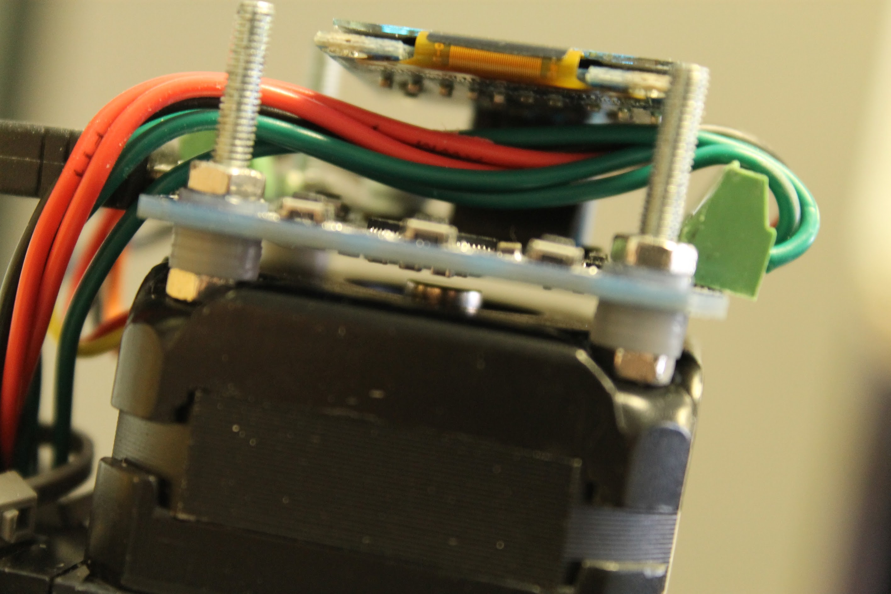
Here's a detail shot of the LCD display of the stepper driver. As silly as it sounds, it takes a lot of the wondering out of a print when you can't see the underside of the build plate to just watch the error counter NOT rise.

Here's what the front of the cabinet looks like. I saved the drawers during the deconstruction phase. I intend to (eventually) remove the faces from the drawers and attach them to the front on hinges with magnetic closures. That will complete the aesthetics of the front while still allowing easy adjustment and maintenance. I kinda of murdered the DMD chip on my previous projector and have since switched to an Acer P1500. I haven't removed any of the internal filters, but I did add about 4mm worth of spacers to the optics and a #1 and #4 macro lens to the front for focusing. You can also see the front side of the projector mount. It's actually an articulated wall mount for a small TV. I completely disassembled it, degreased the hinges, roughened the hinge pins, and then put everything back together as tightly as possible. This has the net effect of making the mount adjustable easily enough in virtually any direction very quickly and easily, but still requiring enough force to move or disturb that it won't do so unintentionally or over time.

Here's a shot of the underside of the vat. You can see the mounting bolts for the vat bottom, the TowerPro SG-5010 servo I used for the shutter. I cut the shutter itself from a piece of aluminum I had laying about. The macro lenses are visible as well, the #1 is on the bottom with the #4 on top.

Three words - dedicated power strip. Learn it. Love it. Each component has it's own dedicated power supply to help prevent power related stalls or crashes, but the strip offers a single switch to turn everything off or on all together and a convenient way to forcibly (read panic) stop the printer if need be.

Here's a close up of the vat itself and the bottom of the axis. I really like the design of the axis here, as it allows lubricant to sort of pool at the lead bearing ballbearing at the bottom. That helps to prevent undue friction and axis sticking.

Here's a shot of the back showing my charmingly trailer-park-ish zip-tie based cable management solution as well as the RPi itself, the adjustable stop screw for the projector positioning, the central power strip, and of course my lonely and misplaced RPi camera module. I haven't quite found a good place to mount it just yet, but at some point I'll probably place it about a 1/4 of the way up from the bottom of the axis and use NanoDLP's dynamic lift feature to bring the build plate up every so often to check the print progress.

Here's a detail shot of the RPi itself. I upgraded my previous build at some point I've now forgotten from an RPi 2 to an RPi 3. I highly recommend the upgrade as the extra RAM and processing power make a fairly noticeable difference in stability and performance, and the built-in WiFi just makes everyone's life easier. I keep the ethernet cord plugged in as a matter of course, just in case. The case I used for the RPi offers cutouts for the camera connector and GPIO headers. I used (I think) a 3.5" floppy IDE cable I had to custom make a header adapter. It's another move I highly recommend as it just seems to simplify and stabilize everything. Remember - heat shrink tubing and careful planning are your friends. But then again, so are hasty frustration and heavy handed use of hot glue, so make yours accordingly.

A close up of the GPIO header cable. You can see I added the error pin after original manufacture. That happened because I included the error pin in my original redesign, and then promptly forgot all about it when I went to build it. Oops.

Here's one side of the projector mount. The mount itself offers 3 degrees of freedom, but I find it most stable to set the rear of the plate farther back than is needed to center the projected image, and then push it forward with the set screw you can see. This effectively places the projector mount under tension and helps to ensure it doesn't drift or waver.

Here's the other side of the above view. You can see the hanging Prolific USB to Serial adapter used to enable the RPi to control the projector. The reason for the quick disconnect and extra wire in between the projector and serial ends is (if I'm being honest) my own straight up laziness. I wasn't paying enough attention when I purchased the adapter and ended up with a male end. We all know that a pole is a pole and a hole is a hole and poles go in holes, but poles don't go in poles. Rather than take the time or spend the energy to find a null modem or even drive back to the store and get the right one, I just soldered it together with a quick connect I had laying around. As the famous quote goes, "it seemed like a good idea at the time."

A few notes about the quirks of this design:
I had originally intended to add a porthole, fan, and screen to the side of the cabinet as an exhaust system for the hot air the projector produces. However, after running several prints I realized that as long as the back of the cabinet isn't too close to anything the hot exhaust from the projector sort of pools in the underside of the cabinet and heats the vat floor which in turn heats the resin in the vat. That has the net effect of lowering the overall surface tension of the resin, decreasing its viscosity, and helping to prevent layers from detaching due to vacuum force and therefore failed prints!
I haven't yet figured up an enclosure for the top side. I've got a small pile of Lexan sheets cut-scraps, so I may screw those into a rough box shape and them apply a UV blocking film of some kind. (I'm WAY open to suggestion here). It can be a bit of a pain at the moment to keep and eye on the printer and make sure nothing ends up in the resin or caught in the axis, but it hasn't been much of a problem so far. Not having a top does have the added fringe benefit of on-printer table space for the inevitable small pile of printer related tools we all have orbiting our printers (alcohol, de-plating spatula, gloves, etc).
Currently I have the projector focused to 37 microns XY, and due to the NZS driver my Z resolution is virtually arbitrary. That gives me an effective printing volume of roughly 70mm x 40mm x 300mm. I haven't taken advantage of it yet, but (at least in theory) due to the exceptional length of my Z axis I could plate up a truly impressive "tree" of prints and print them 300mm high.
I hope this helps, or at least serves as a good example (of to do or not to do, whichever). If there are questions I'm happy to answer them, if there are suggestions I'd love to hear them.
Last edited by backXslash (2021-12-29 02:03:23)
Offline
#2 2017-03-17 08:03:23
- Shahin
- Administrator
- Registered: 2016-02-17
- Posts: 3,556
Re: Rebuild Log: Or, What Tony Stark Did In A Cave With A Pile Of Scraps
Great setup, thank you for sharing.
1. What are the effects of installing macro lens, just closer focus or also sharper images on the corner?
2. About nano zero stepper, do you have any sample with same setup without this stepper to compare practical effect of the driver?
Offline
#3 2017-03-17 13:33:44
- backXslash
- Member
- Registered: 2016-03-25
- Posts: 151
Re: Rebuild Log: Or, What Tony Stark Did In A Cave With A Pile Of Scraps
Great setup, thank you for sharing.
1. What are the effects of installing macro lens, just closer focus or also sharper images on the corner?
2. About nano zero stepper, do you have any sample with same setup without this stepper to compare practical effect of the driver?
Those are both excellent questions.
The macro lenses help with closer focus. The Acer P1500 is kind of known for running hotter than most in terms of unmodified UV output, but also for being more than a little difficult about edge blurriness.
The mount I have it on has a ball and socket joint as it's final linkage before the projector. That allows me to really tweak the relative positioning of the optic path in relation to the vat bottom. Also, I've basically got the lenses attached with what amount to gecko tape so that they're not static. I can move them around and help compensate (a little) for edge distortions.
Between those factors I've got the entire build plate in crystal clear focus. However, I'm having an issue right now with the projected image not being uniformly square. I'm getting what amounts to a "handlebar moustache" distortion of the squareness that can't be compensated for with the projector's keystoning features. I'm thinking it MAY be introduced by some quirk of optics in the interaction between the factory designed lens path and the +4 macro lens.
My next experiment was actually going to be getting my hands on a rectilinear lens and experimenting with that. If that didn't help, I had intended to show you a few tutorials I found for programming image manipulation software that would hopefully allow NanoDLP to get rid of that distortion in software.
As for the prints, yes I do, I just can't find them. The "ringing" effect that you some times see on vertical surfaces is virtually absent. Also the overall print itself is more uniform in both quality but also defects, i.e. if a print has a layer detatchment or aberation somewhere, rather than being luck-of-the-draw as they sometimes are, it will be in the same place in every print. That kind of consistency helps me model out any problem areas or tweak them away in software in NanoDLP itself.
Most of us use some type of threaded rod, leadscrew, or ball screw for our Z axis. Stepper motors have a mathematically inarguable relationship between step size and linear movement for that given rotation. The answer to overcoming or mitigating that has always been microstepping, but a microsteped stepper loses torque at a ridiculous rate the more its full steps are divided. That essentially means that while you'll almost always end up in the same place if the total distance moved is evenly divisible by your motors full step movement, it's an effect of averages.
The NZS is a closed loop system. I have it set to 1/16th micro stepping purely for the quieting effect that has on the motor. However, it controls both coils on the motor in response to its encoder, not the micro stepping value. That means that once the motor reaches the degree of rotation indicated by the step pulses, it forcibly locks the poles in place and holds them there. That means each layer is exactly, precisely, repeatably the same height with a deviation so small I'm not sure how to calculate it.
It's actually pretty cool, I'll try and record it so you can all hear what I'm talking about. During a print, you can actually hear when the NZS is holding the motor in a place it doesn't naturally want to be. It doesn't no harm to the motor, but it is clearly and audibly different from the behavior of any other driver I've tested.
What that all adds up to is print failure prevention. I'm printing at 24 micron layers because I seem to get a much better layer-cure-uniformity that way which allows me to print the extremely fine filigree jewelry designs I specialize in. If my axis isn't consistent enough, I find that layers will or fail to adhere not everywhere but selectively. That results in a piece coming out with large holes in the filigree, which is equivalent to a failed print. With the more consistent layering, my repeatability is rock solid, which means that once I tweak a given print to "perfect" then I can save those settings in their own profile and never worry again about that print not coming out.
Last edited by backXslash (2017-03-17 13:48:26)
Offline
#4 2017-03-17 17:45:17
- Shahin
- Administrator
- Registered: 2016-02-17
- Posts: 3,556
Re: Rebuild Log: Or, What Tony Stark Did In A Cave With A Pile Of Scraps
We have worked on distortion correction algorithm before. Generally it has two big issues.
1. Distortion correction algorithms are expensive to run and require lots of inputs from users to make it works which makes them very difficult to use.
2. Resolution drop - We will lose some resolution on corners which makes things unpredictable quality wise.
So software / optical distortion corrections somehow similar to software / optical zoom implementations.
Will try nano zero stepper, thank you.
Offline
#5 2017-04-19 08:53:53
- Yianni-VJ
- Member

- Registered: 2016-05-24
- Posts: 95
Re: Rebuild Log: Or, What Tony Stark Did In A Cave With A Pile Of Scraps
Hi backXslash,
You have done so much with so little, very impressive !
Following your example I also got one of those NZS, I like it a lot ![]()
I think I would feel more comfortable using an Arduino shield on my build, do you happen to know if mUVe/Marlin firmware supports an error pin?
If not, are there any alternatives that support both the error pin and "Z_move_comp" response ?
Offline
#6 2018-02-05 16:09:57
- CoraDias
- Member
- Registered: 2018-02-05
- Posts: 1
Re: Rebuild Log: Or, What Tony Stark Did In A Cave With A Pile Of Scraps
Hi...i am a new user here. In my case i observed NZS is a closed loop system. I have it set to 1/16th micro stepping purely for the quieting effect that has on the motor. However, it controls both coils on the motor in response to its encoder, not the micro stepping value. That means that once the motor reaches the degree of rotation indicated by the step pulses.
Last edited by CoraDias (2018-02-26 22:13:51)
Offline