You are not logged in.
- Topics: Active | Unanswered
#26 2016-08-18 16:57:48
- Shahin
- Administrator
- Registered: 2016-02-17
- Posts: 3,556
Re: Auto Mask Generation
I have done some changes. It should works close to ideal.
Offline
#27 2016-08-19 02:05:28
- lcluff2000
- Member
- Registered: 2016-04-16
- Posts: 53
Re: Auto Mask Generation
So I gave it a shot. Here's my feedback...
* I clicked on the [Turn Projector On], then [Display] projector calibration grid, then [Mask Generator] button
* It stayed on the projector calibration grid
* then clicked in a visual grid cell, then the grid came up with that cell highlighted, then a couple of seconds later the mask came up
* then clicked in a visual grid cell, then the grid came up with that cell highlighted, but the grid stayed up this time
* then typed 256 into the grid cell (I used the middle cell) and hit [enter]
* I expected the square on the DLP to go black, but it did not seem to change intensity at all
* Then I clicked [Preview], nothing happened, I expected the mask to display on the browser or the DLP.
* I waited for about a minute and then the mask came up with a square cell darkened in the middle of the projection (I was expecting a dark point circularly fading about 1/2" in diameter)
* The DLP flickered several times while I was typing this out
Suggestions:
* Darken/lighten the square of light real-time each time as the user types a value in a corresponding cell (the user will have their light sensor on that spot to see if it is the right value before adjusting the next cell value)
* Highlight the selected cell by some other indicator than brightness (for example, put a red dot by it, or a red rectangle around it). In this way, each square on the DLP reflects the brightness value the user indicates in each cell. With this capability, the user can verify adjacent cells, or compare adjacent cells.
* The up/down arrows are really nice, but they are so small on my screen, I can't click on them (I have a 4K screen)
* When generating the mask, assume the center pixel on the square is the value in the cell, then interpolate from that point to the values defined by the center of each adjacent cell). The excel sheet I provided has an interpolation algorithm that you may be able to use.
* Have some sort of progress bar to indicate the mask is being generated
* Kill the mask generation if they move off the mask generation form (so it doesn't pop up suddenly when they are doing something else)
* Maybe allow mask generation to be cancelled?
I hope these suggestions are helpful!
I'm really excited to see this feature being implemented!
Offline
#28 2016-08-19 04:50:10
- Shahin
- Administrator
- Registered: 2016-02-17
- Posts: 3,556
Re: Auto Mask Generation
Thank you for the feedback.
* Darken/lighten the square of light real-time each time as the user types a value in a corresponding cell (the user will have their light sensor on that spot to see if it is the right value before adjusting the next cell value)
* Highlight the selected cell by some other indicator than brightness (for example, put a red dot by it, or a red rectangle around it). In this way, each square on the DLP reflects the brightness value the user indicates in each cell. With this capability, the user can verify adjacent cells, or compare adjacent cells.
I agree having correct brightness will be helpful but we do not know range of values users will going to enter so until all square filled we could not display brightness correctly. Also I believe it will be confusing for the users. Instead I have made preview button display very fast to help measure correctness of values.
* The up/down arrows are really nice, but they are so small on my screen, I can't click on them (I have a 4K screen)
These are native html5 controls, It is not possible to modify them. I suspect your browser is not customized for 4K screen or something. Could you share screenshot, maybe we could play with size of box itself.
* When generating the mask, assume the center pixel on the square is the value in the cell, then interpolate from that point to the values defined by the center of each adjacent cell). The excel sheet I provided has an interpolation algorithm that you may be able to use.
First plan was that, but these kind of algorithms are very slow on RPi, I already tried couple of different ways, but if you could provide pixel level implementation in golang we could try ![]()
Also as we place sensor by hand to take measurement, it will never be center of square so having algorithm working from exactly center would not make generated mask more realistic.
* Have some sort of progress bar to indicate the mask is being generated
* Kill the mask generation if they move off the mask generation form (so it doesn't pop up suddenly when they are doing something else)
* Maybe allow mask generation to be cancelled?
I have tested algorithm on amd64 before updating beta version. I did not expect it runs this slow on ARM. I have done some changes, now it takes under 30s to render mask. Also I have separated preview logic, so it prepare image without going through heavy optimizations.
Offline
#29 2016-08-19 06:05:30
- lcluff2000
- Member
- Registered: 2016-04-16
- Posts: 53
Re: Auto Mask Generation
I agree having correct brightness will be helpful but we do not know range of values users will going to enter so until all square filled we could not display brightness correctly. Also I believe it will be confusing for the users. Instead I have made preview button display very fast to help measure correctness of values.
I'm not understanding why the corresponding brightness (greyscale) cannot be displayed correctly on the DLP grid square when a user types a value between 1-256?
With the current method, I think the problem is going to be the iteration time. If the user has to push the preview for every value they enter so they can take a measurement with their sensor, it will take a long, long time to determine each cell value. For one cell, the user will have to enter a value, generate the mask, measure a value, over and over until the sensor reads the right value for that cell position. In addition, the mask won't be right because the values in the adjacent cells may not be right yet.
If the user enters a value and that changes the greyscale immediately on the DLP square the iteration time is much faster.
But, I also agree that the interpolation is going to make the brightness be different than having the square all one greyscale value. Although, the result may be close enough without worrying about the interpolation.
So, I have an idea that might make mask generation fast, that may also help the issue with iteration time. If you have access to a image re-size function, you can make a small image using the measured values (10x5 pixels), then use re-size to scale it up to the 1920x1080. I have found when experimenting that re-size is very fast and performs interpolation automatically.
Example of 10x5 image
Example of 192x108 image (your site doesn't allow 1920x1080 images)
I used this site to re-size the image
http://resizeimage.net/
If the mask generation algorithm is fast enough, then you could apply the mask to the grid displayed on the DLP whenever the user entered a value in a cell (AND each pixel on the mask with the grid image).
Here is a screenshot of the up/down arrows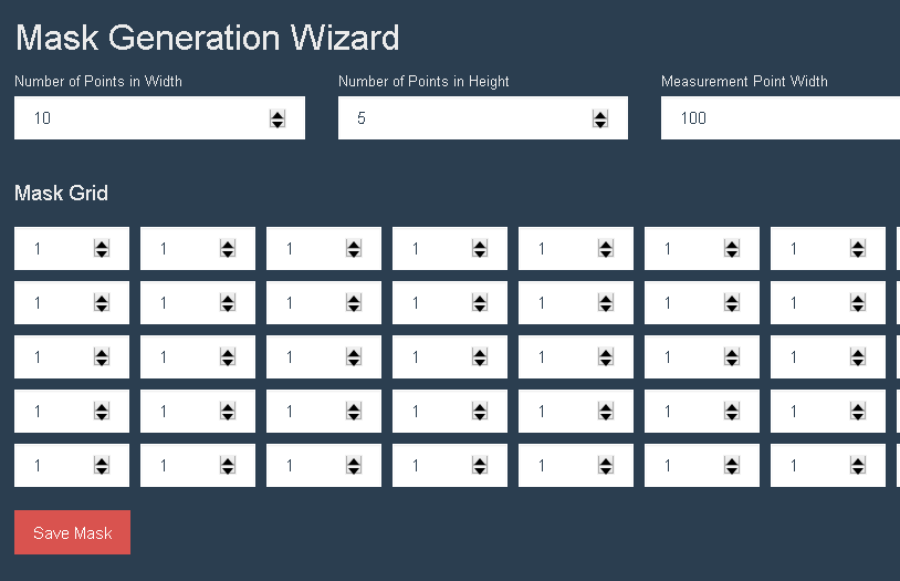
Offline
#30 2016-08-19 06:30:07
- Shahin
- Administrator
- Registered: 2016-02-17
- Posts: 3,556
Re: Auto Mask Generation
I see you have not upgraded to the latest version yet ![]()
Your resizing idea is awesome.
Let me go through my assumptions and implementation.
User could enter any float (64bit) number, not just 1-256. Final result will be 0-255 grayscale image but I am not sure if all uv sensor reads value from 0-255. So to instead of forcing user convert value they read to 0-255 format, they can enter any value.
We find out lowest value and try to bring all brightness close to lowest value after they have filled whole grid. So user does not need to preview image at all maybe once just at the end of measurement to make sure everything is correct.
I think we have two different idea.
Yours
1. User scan whole surface to find out lowest value on the surface.
2. Measure the first point and try to adjust value to make it brightness match lowest value on the surface. Will do same thing for all other points.
Mine
1. User enter whatever her/his sensor reads into the grid, one by one.
2. At the end press preview to make sure nothing require adjustment by scanning surface with sensor
I do not have first hand experience in uv sensor usage so let me know which way is easier to use.
Offline
#31 2016-08-19 11:50:39
- lcluff2000
- Member
- Registered: 2016-04-16
- Posts: 53
Re: Auto Mask Generation
Not yet. I can try that later this afternoon (it's 5:30am). ![]()
My sensor read values from 0.6 to 3.81 across the surface of a DLP grid. I found that the sensor readings were non-linear and I had to experiment and use a regression generator to get a formula to get the right greyscale values. Here is the formula:
greyscale = 20* (-0.1282*x^5+1.6196*x^4-7.843*x^3+17.8275*x^2-16.3317*x+4.75)
Even that formula was not perfect.
The problem is neither you nor the user will know the linearity formula for their sensor.
Using my method, you do not have to know the formula because the user will enter values (1-256) in a cell to get the right greyscale value so their sensor shows the right value.
If you use your method, you will need a way for the user to enter a linearity formula. Then they will have to experiment over and over entering different formulas until they get the right formula.
I suggested my method to avoid this challenge of having to determine a linearity formula.
Offline
#32 2016-08-19 14:35:04
- Shahin
- Administrator
- Registered: 2016-02-17
- Posts: 3,556
Re: Auto Mask Generation
I hoped for linear reading. I will change the implementation.
Offline
#33 2016-08-19 19:49:19
- Shahin
- Administrator
- Registered: 2016-02-17
- Posts: 3,556
Re: Auto Mask Generation
Implementation changed.
Offline
#34 2016-08-20 01:44:58
- lcluff2000
- Member
- Registered: 2016-04-16
- Posts: 53
Re: Auto Mask Generation
Cool! This is getting there!
Here's some feedback:
* It threw me off a little that when you press enter in a cell it generates the mask. I finally realized I have to type a value and wait (without pressing enter) so the grid DLP cell changes without generating the mask. The up/down arrows are nice (just really small on my 4k screen)
* I like the blue outline, except is is really hard to see at full brightness (value=256)
* Can you persist/store the cell values? This would allow the user to go in/out of mask generator to do things like turn on/off projector w/o losing settings, or come back later to adjust settings a little.
* When the mask generates, it is "blocky" (ie not a useable mask) Do you have plans to use an image resize to create the mask?
* Nothing seems to happen when I click [save mask]. I expected it to change the mask on the Setup...Projector Mask screen.
I hope that is helpful!
Regards
Larry
Offline
#35 2016-08-20 08:37:00
- Shahin
- Administrator
- Registered: 2016-02-17
- Posts: 3,556
Re: Auto Mask Generation
* It threw me off a little that when you press enter in a cell it generates the mask. I finally realized I have to type a value and wait (without pressing enter) so the grid DLP cell changes without generating the mask. The up/down arrows are nice (just really small on my 4k screen)
I put some additional info about automatic update on help page. Try another browser, I think it is something to do with your browser or OS settings as arrows rendered and positioned by browser itself.
* I like the blue outline, except is is really hard to see at full brightness (value=256)
Changed it to a darker color.
* Can you persist/store the cell values? This would allow the user to go in/out of mask generator to do things like turn on/off projector w/o losing settings, or come back later to adjust settings a little.
I do not think it worth development time, grid rendered by javascript and not backend so saving that will take some development time. You can keep browser tab open and restart printer using another tab.
Generating mask is a rare task, once per projector I guess.
* When the mask generates, it is "blocky" (ie not a useable mask) Do you have plans to use an image resize to create the mask?
* Nothing seems to happen when I click [save mask]. I expected it to change the mask on the Setup...Projector Mask screen.
Clicking on save cause non-blocky image to be saved on /static/plates/mask.png path (it will takes around 30s). It will be used as default mask file which you could inspect on setup page / mask tab.
Offline
#36 2016-08-20 11:08:34
- Xmike
- Member
- Registered: 2016-03-25
- Posts: 97
Re: Auto Mask Generation
@lcluff2000
May I ask what sensor you are using . With my UV sensor unfortunately I have no good experiences.
Since the DLP chip emits the light at a certain frequency,
the measurement results of my sensor at the same measuring point are very different.
Offline
#37 2016-08-20 13:53:00
- lcluff2000
- Member
- Registered: 2016-04-16
- Posts: 53
Re: Auto Mask Generation
I use this sensor I got off of eBay: ML8511 UVB UV Rays Sensor Breakout Test Module
Shahin, looks like for build 1218 the blocky mask is being stored when [save mask] is pressed and then displayed on Setup..Projector Mask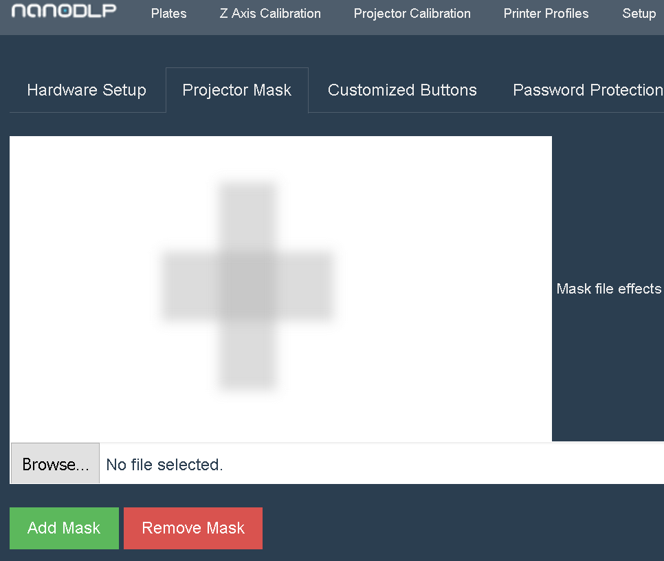
(On this test, I put value 200 in center cell and 220 on each side)
Offline
#38 2016-08-20 14:00:33
- Shahin
- Administrator
- Registered: 2016-02-17
- Posts: 3,556
Re: Auto Mask Generation
It is 10% of pixel blur on sides. It is much more smooth than upsizing pixels. Are you sure we need more smoothing? My guess is difference should be normally around 10-15% from center to sides. So final result will be much smoother.
Offline
#39 2016-08-20 15:44:31
- lcluff2000
- Member
- Registered: 2016-04-16
- Posts: 53
Re: Auto Mask Generation
Are you sure we need more smoothing?
Actually, I'm not sure. This is a good question. I think it is all about resin cure. The more even, the less chance of over cure or under cure or "shelves" that may cause stress in the part. As a mitigation, I suppose additional cells can be added to the grid to make the result even smoother?
I think I'm going to ask an expert I know on resin cure to see what he thinks.
I also plan to experiment some more to see what my sensor sees when a full mask is completed and displayed.
Offline
#40 2016-08-20 17:24:48
- lcluff2000
- Member
- Registered: 2016-04-16
- Posts: 53
Re: Auto Mask Generation
Here is the mask I generated with Nanodlp: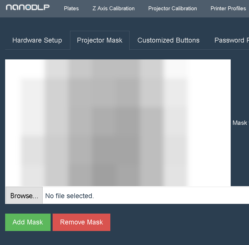
So I decided to see what this would look like with the resize algorithm... I followed this process...
Create a PGM file by inserting the values you entered into Nanodlp (make sure to have .PGM as the file extension)
test27.pgm.txt
Convert the PGM to PNG (select color=gray):
Use this URL: http://image.online-convert.com/convert-to-png
The image is very tiny right below this text
Resize to 1920x1080 (select png file from above, section 4 uncheck "keep aspect ratio" & enter 1920 & 1080, section 6 select PNG, section 7 select Lossless Compression, click [resize image] then [download image])
Use this URL: http://resizeimage.net/
Offline
#41 2016-08-20 17:55:39
- Shahin
- Administrator
- Registered: 2016-02-17
- Posts: 3,556
Re: Auto Mask Generation
Could you display both masks and checkout the result with your uv sensor?
Offline
#42 2016-08-21 03:53:21
- elliot
- Member
- Registered: 2016-04-28
- Posts: 109
Re: Auto Mask Generation
Wow! wow! Guys this is great! I hope it's okay to glom on this thread and ask/inject some of my experiences on this...
I'm just starting to do the same mapping for my Viewsonic. I started off doing measurements with the spectrometer from public labs. (https://publiclab.org/wiki/spectrometer) With this I tuned in the projector settings allowing increased blue light shift that was a stable curve between 390-450nm. (Because the UV sensor from spark is best up until about 390 (ML8511) - after which the sensitivity falls off rapidly). It's probably best to choose a smooth curve over this area since most resins used for the DLPs cure at 405nm (or are at least targeted for this wavelength). I'll go in and list those settings I found to be best for the curve in a separate message.
I also made a mount for the UV sensor with measurement tabs on the sides to allow easier identification of where the sensor is being placed on the grid. Again, if you guys are interested I'll post this handle in stl in a separate post.
Just to make sure I'm caught up with the journey thus far. We are all trying to normalize the intensity of the UV across the mask. The current method is to use the lowest value and reduce brightness on the other areas...I just wanted to ask, if we start with a brightness value of 20% could we not adjust up and down to make it easier? If the lamp operates on a curve for intensity, a beginning default of higher brightness (50+) to start off might be adding to this polynomial solution of ^5 power and thus the error.
I hope I'm helping...
Elliot
Offline
#43 2016-08-21 04:37:57
- lcluff2000
- Member
- Registered: 2016-04-16
- Posts: 53
Re: Auto Mask Generation
Could you display both masks and checkout the result with your uv sensor?
Is there an easy way to display the mask I upload on the DLP?
With this I tuned in the projector settings allowing increased blue light shift that was a stable curve between 390-450nm. (Because the UV sensor from spark is best up until about 390 (ML8511) - after which the sensitivity falls off rapidly). It's probably best to choose a smooth curve over this area since most resins used for the DLPs cure at 405nm (or are at least targeted for this wavelength). I'll go in and list those settings I found to be best for the curve in a separate message.
I've heard too that resin cures at 405nm and that the ML8511 falls off around 390nm. My plan was to purchase a bandpass filter at around 400nm that I would put over the ML8511 sensor (mine is on order).
I also made a mount for the UV sensor with measurement tabs on the sides to allow easier identification of where the sensor is being placed on the grid. Again, if you guys are interested I'll post this handle in stl in a separate post.
I was planning to make a mount for my sensor as well, I'd love to see your stl information!
Just to make sure I'm caught up with the journey thus far. We are all trying to normalize the intensity of the UV across the mask. The current method is to use the lowest value and reduce brightness on the other areas...I just wanted to ask, if we start with a brightness value of 20% could we not adjust up and down to make it easier? If the lamp operates on a curve for intensity, a beginning default of higher brightness (50+) to start off might be adding to this polynomial solution of ^5 power and thus the error.
Yes, we are trying to normalize the intensity of the UV across the floor of the resin vat (preferably at 405nm). I'm not sure I understand your question about brightness. I'm not sure if brightness is proportional to UV intensity. But, if it is, it seems like you would want the most brightness you could get 100% (so the resin will cure faster). Then wherever brightness (UV intensity) is hot, we damp that down to get an even brightness (UV intensity) across the floor of the resin vat. So, we could end up with 50% overall brightness (UV intensity) for example.
I think one of the cool things about the method Shahin has implemented, is that you don't care about the linearity of the sensor or the lamp. The user simply changes the greyscale value until the sensor reads the right value at every grid point.
Offline
#44 2016-08-21 04:52:13
- elliot
- Member
- Registered: 2016-04-28
- Posts: 109
Re: Auto Mask Generation
Thanks Larry-
Re: band pass- Would that work, I had thought of that. But if the sensor cuts off at 390 it still doesn't register above that value...correct?
Re: Stl I'll post shortly
Re:Brightness
So what I found is that with higher brightness settings in the viewsonic, even with high contrast, the bleed-out overcomes the contrast...black is not black anymore. So high brightness affects other areas. So what I'm trying to do is find the sweet-spot that allows reasonable curing times while having very good control over light transfer to other areas you don't want cured. We have to assume that the light is being refracted as it enters through the glass and then the resin. I'm starting to work with some lenses that allow better collimation of the beam without dispersion. So if we get the filters on the viewsonic right, and have basically the highest tolerable UV band when black is black. That's the sweet spot. Then Start with brightness (lamp intensity) around 20-40% we should be closer to having a normalized projection. Maybe I'm not understanding how the greyscale is being done...is this basically a contrast setting customized for different areas of the Ti chip?
Thanks!
Elliot
Offline
#45 2016-08-21 05:05:17
- elliot
- Member
- Registered: 2016-04-28
- Posts: 109
Re: Auto Mask Generation
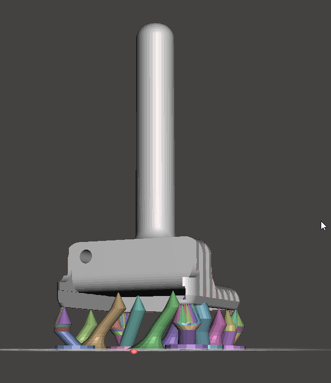
UV sensor handle. Can I upload the .STL to the attachments and submit to you guys that way? (Sorry this method of forums is new to me)
Offline
#46 2016-08-21 05:11:22
- lcluff2000
- Member
- Registered: 2016-04-16
- Posts: 53
Re: Auto Mask Generation
Elliot,
Re: bandpass - Looking at the curve for the sensor, the 405nm output will be about 20% of the output for 390nm, but there should still be an output. At least that is my hope.
Re: stl - Super! Thanks!
Re: brightness - I personally haven't played with brightness. I can conceptualize the bleedover situation you describe. I'm not quite sure how this maps to even UV intensity across the entire vat bottom? I think bleedover might be very local (millimeters) and lamp intensity is across the entire vat bottom (multiple cm)? The greyscale is being done by projecting the mask verses just a blank white rectangle. Any time a slice is projected it does a boolean AND of each pixel on the mask with each pixel on the slice. The mask is created by the method described in prior posts. I'm no expert at this stuff, so hopefully this is making sense...
Regards,
Larry
Offline
#47 2016-08-21 05:14:32
- Shahin
- Administrator
- Registered: 2016-02-17
- Posts: 3,556
Re: Auto Mask Generation
You can use "upload image" button on plates page to display any image.
Offline
#48 2016-08-21 05:16:26
- elliot
- Member
- Registered: 2016-04-28
- Posts: 109
Re: Auto Mask Generation
Right- So on the band pass- this is why I was going for the smoothest curve over the range. (I'll post some of the spectrum tomorrow or next week - getting late here!) My thoughts were if it was a stable line and equal between 390 and 405 - then I don't need a band pass.
So I think what's happening is contrast plays against brightness - to a point - and then one can supercede the other if it's a large difference - like 10% vs 90%. I believe the greyscale is contrast/brightness - but maybe someone else can chime in here.
Offline
#49 2016-08-22 13:04:26

Re: Auto Mask Generation
You can try mask generation feature on the beta version on projector calibration page.
It is not perfect right now, one the edges we need some smoothing/blurring and etc.
Great JOB Shahin !
I have couple Ideas for precise positioning UV sensor .
first
is to use small linear actuator X and Y which hold UV sensor and have position holes same tray for resin ,
when we choose frame in grid the sensor rapidly move in that place by actuators.

second
is make stencil from any plastic or metal by laser cutting aganse with position holes same tray for resin ,
and hold UV sensor in tapered shape , which will center sensor in stencil exactly in mid of each one

Last edited by DLprinter (2016-08-22 13:29:55)
Offline

